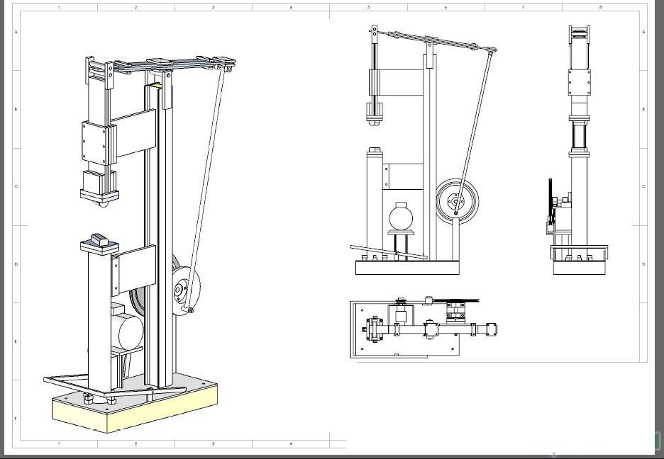
Forging electric hammer with their own hands. Detailed drawings and description for self-manufacturing.
hammer frame
The hammer frame is welded from a channel 100 * 50mm.
Lengths and number of pieces required:
2000- mm - 2 pcs.
900 mm - 4 pcs.
600 mm - 2 pcs.
500 mm - 2 pcs.
400 mm - 3 pcs.
375 mm -2 pcs.
Before welding the stop under the hub into place, it is necessary to weld and install the structure shown in fig. 4.
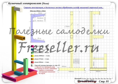
Rice. 1 Forging electric hammer frame.
After welding the frame structure, weld places in accessible places using a grinder.
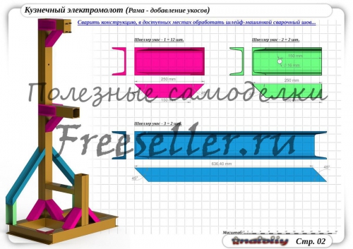
Rice. 2. Hammer frame with the addition of cuttings.
Main elements of the machine
1) guide . Weld a part 150x150x200mm from four plates. weld the bottom of the guide to the bottom of the part (the bottom is made by analogy with the cover of the corner 25x25 mm).
2) Hammer- weld two corners 100x50 mm 700 mm long between each other by first making cutouts and holes according to the dimensions in the diagram.
3) Anvil- weld the anvil to the bottom of the hammer and the frame (see fig. 3)
4) Dural plate (setting) - insert 4 plates inside. Adjust (adjust) the direction of the hammer with bolts (when adjusting, the hammer should not dangle from side to side, and should not be clamped). After adjustment with nuts, fix the position of the bolts.
5) Guide cover- weld a frame from four blanks of a 25x25 mm corner and fix it in the upper part of the guide.
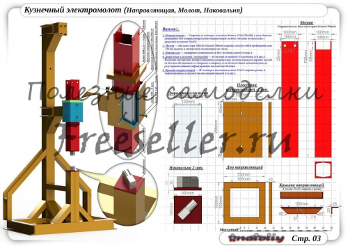
Fig.3 Forging electric hammer (Guide, hammer, anvil)
Carriage
The carriage is welded from corners 50x50 mm.
Dimensions and number of blanks from the corner:
850 mm - 2 pcs.
500 mm - 2 pcs.
300 mm - 2 pcs.
240 mm - 1 pc.
235 mm - 2 pcs.
100 mm - 2 pcs.
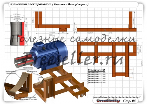
Fig.4. Forging electric hammer (carriage-motor/brake)
Translational mechanism
Consists of
swing
rear wheel shock absorber
Upper and lower connecting rod. And other items.
For explanations on this node, see Fig.5,6,7, 8.
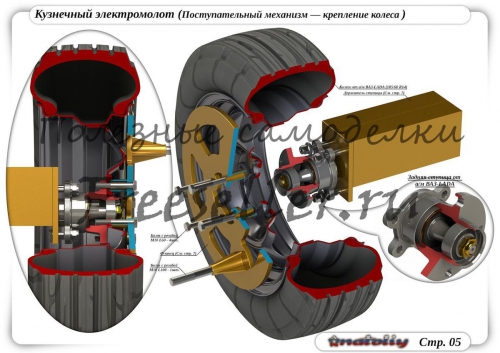
Fig.5 Forging electric hammer. Progressive wheel mounting mechanism.
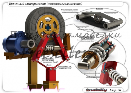
Rice. 6 Forging electric hammer. Progressive mechanism.
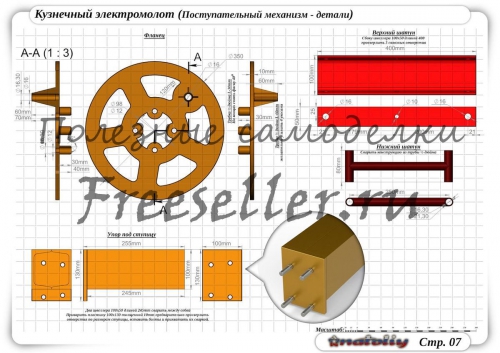
Rice. 7 Forging electric hammer. Details of the forward mechanism.
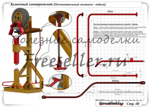
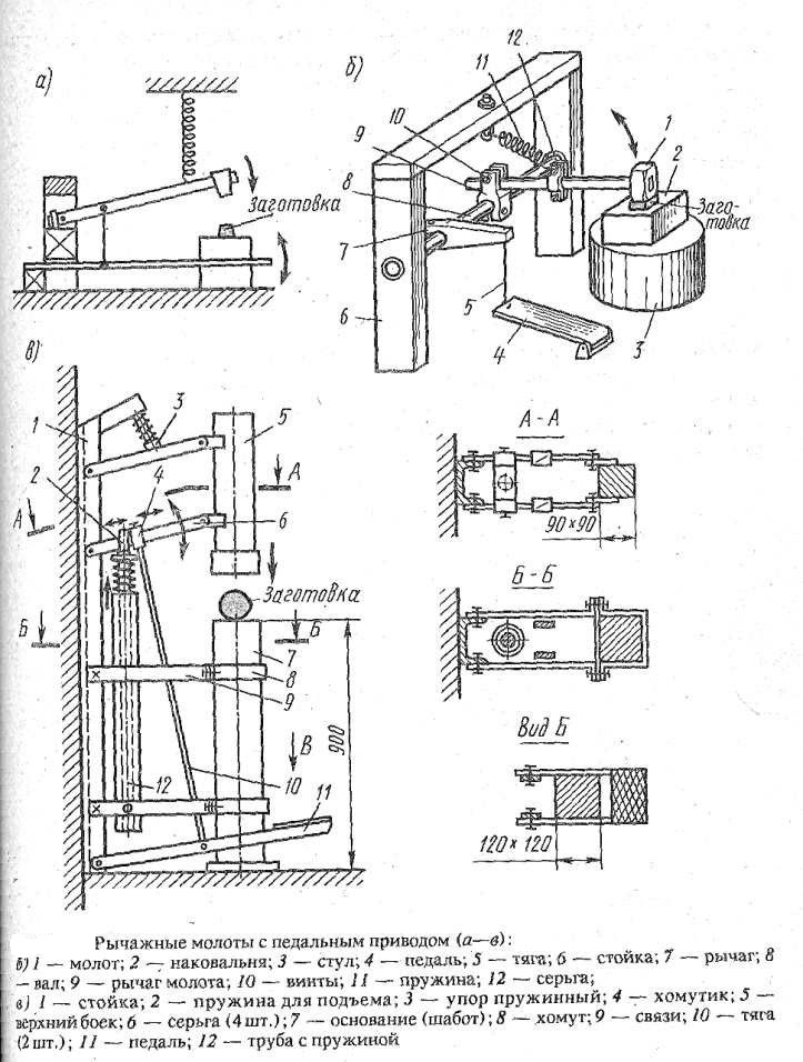
Fig. 8 forging electric hammer. Progressive pedal.
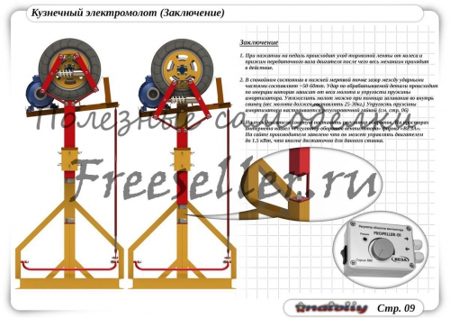
Conclusion!!!
1) When you press the pedal, the brake band leaves the wheel and the engine transmission shaft is pressed, after which the entire mechanism comes into action.
2) In a calm state at the bottom dead center, the gap between the impact parts is ~ 50-60 tons. The impact on the workpiece occurs due to inertia, which depends on the plumb of the hammer and the elasticity of the shock absorber spring. You can make the hammer heavier by pouring lead into it (the weight of the hammer should be 25-30 kg)
The elasticity of the shock absorber spring is adjusted by the adjusting nut (see Fig. 6)
3) I advise you to put the speed controller on starting the engine. On the Internet, I found a Veza fan speed controller. The manufacturer's website states that it can drive a motor up to 1.5 kW, which is quite enough for this machine.
It is almost impossible to completely copy the scheme of a double-action forging hammer at home. But the drawings of a mechanical hammer of a simple action, even with el. driven, are simple, and therefore quite accessible for practical implementation by a home master.
Choosing a Hot Metal Deformation Method
Free forging of small-sized products can be implemented on the following forging machines:
- pneumatic hammer with el. driven;
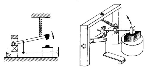
- manual mechanical hammer (with a solid / flexible rod or spring version);
- screw hammer.
The latter option is characterized by the lowest speed of movement of moving parts, and therefore can only be used for forging highly ductile metals. It remains to make either a pneumatic hammer or a mechanical hammer of simple action.
Comparing the technological indicators of deformation, it is easy to conclude that the impact energy for a spring hammer is significantly lower than for a pneumatic hammer. In addition, the presence of e. management in the latter case will significantly reduce physical activity.
In contrast to the pneumatic hammer, the spring version does not require significant initial costs, and is also safer to use. For such a unit does not require email. motor, and this will make it possible to subsequently save on energy resources.
The main questions on how to make a homemade blacksmith hammer are discussed below.
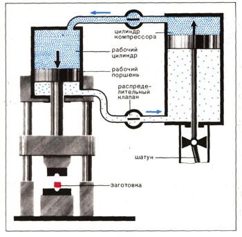
Making a pneumatic hammer
The capabilities of this equipment will be determined by the design of the compressor, which will supply the air distribution mechanism with energy.
A set of drawings in this case should be developed regarding the following nodes:
- beds (it is better to design a do-it-yourself blacksmith hammer with a welded bed);
- working cylinder, selected according to the desired impact energy;
- stock;
- pipelines;
- control systems;
- Saturday.
On the Internet, you can find suitable drawings of an air hammer with el. drive. If they are not, then the design is carried out in the following sequence:
We select a compressor: the compressed air consumption should be approximately 5 ... 6 times the volume of the working cylinder. That, in turn, depends on the required pressure on the metal. For example, for steel, it must be at least 30 MPa, therefore, minimum diameter the rod is 120…150 mm, with a stroke of 150…200 mm (a further increase in the stroke, of course, will increase the kinetic energy, but along the way will also cause a significant increase in the height of the equipment). Therefore, the pressure of compressed air must be at least 6 atm; it will increase if the compressor is located at a distance from the forging unit, since in this case there will be losses of compressed air in the pipelines.
Email the compressor motor must provide it long work, since piston jamming will cause the unit to fail, and blows to the cooled forging will not be effective.
The assembly process will consist in welding the working cylinder to the welded frame of the pneumatic hammer. It must be done very high quality, because under constant shock loads, the seams can disperse.
The main difficulty in manufacturing lies in the preparation and manufacture of the stem itself. It can be made from a power rod from decommissioned crane equipment: they are made from the same types of steels and have approximately the same overall dimensions.
Making a mechanical hammer
The most affordable design is a spring-type mechanical hammer: it is compact and can be quite productive: el. the drive can provide up to 200 ... 300 strokes per minute.
Homemade blacksmith hammer spring type with electric drive consists of:
- Email engine that controls the rotation of the crankshaft.
- Actuating mechanism for generating vibrations.
- Springs (use automotive, not having cracks and delaminations of metal).
- Striker with a system of guide elements.
- Beds of T-shaped type.
- Chabot or lower plate, where the actual forging is performed.
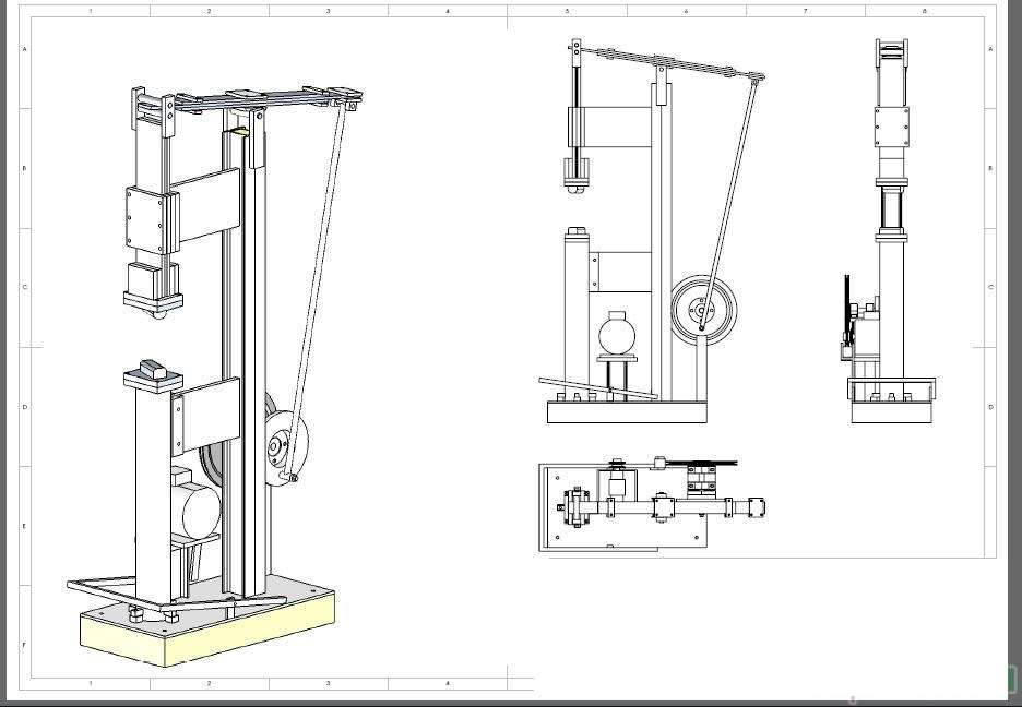
Download spring hammer drawings
A forging hammer is a percussion machine that plastically deforms metal heated to forging temperatures. Such machines are simple in composition, and therefore they are distinguished by high repair resistance, as a result of which they are often used in forging and hot stamping enterprises.
Classification and types
Depending on the type of energy carrier used, the following types of the described units are distinguished:
- , which uses the energy of superheated steam.
- , the energy carrier of which is compressed air.
- , deforming the workpiece by the force of the flow of the working liquid medium (water or oil).
- hydraulic screw hammer, where, along with the energy of the liquid, mechanical energy is also applied.
- mechanical hammer, for which the principle of direct conversion of potential energy/work into kinetic energy is implemented.
Classification is also carried out according to the technological purpose; this determines the design features of the hammers. In particular, forging hammer has free-standing racks, and the steam-air hammer differs in the execution of racks connected to the chabot with the help of fasteners, spring-loaded parts.
The layout principle of all hammers is mostly vertical. A few variants of horizontal hammerless hammers - impactors - have not received much distribution. The reason is the difficulty of holding the heated workpiece during its processing by pressure. At the same time, ground and foundation shaking is significantly reduced, which makes working on such equipment more comfortable.
Structural components
According to its design, a typical blacksmith hammer consists of the following units:
- power cylinder;
- stock;
- two side racks;
- Saturday;
- women;
- control systems.
In the cylinder, the pressure created by superheated steam is redistributed, with the direction of the energy carrier flow into the lower cavity, with which the rod is rigidly connected. On the opposite part of the rod, a hammer head is fixed, which performs reciprocating movements, thereby deforming the material. The forging hammer is distinguished by the presence of smooth strikers, while the steam-air hammer is equipped with a special tool - a forging die.
The current positioning is carried out by special guides on the side posts with a developed contact surface. Similar elements are also provided on the side surfaces of the woman, as a result, fairly accurate blows are applied to the heated blank.
The chabot is a large and massive cast-iron part: for operational reasons, the mass of the chafer must be at least 10 times greater than the mass of the falling parts. To reduce vibrations, the chabot is placed deep into the ground and mounted on a vibration damper, which is taken as large oak boards of square section.
Sequence of action
The forging hammer has a rather complex control system, which requires a high production qualification and proper experience from the blacksmith. The fact is that any steam-air distribution mechanism constantly functions in the cycle of idle and working swings. The difference between them is in the oscillation amplitude: in the idle cycle it is, depending on the power of the unit, 10 ... 50 mm, and in the working cycle it is determined by the initial height of the forging. Since this parameter decreases with each new impact, and the metal cools, the force of the next impact must be greater, and this depends solely on the angle of rotation of the lever that blocks (fully or partially) the openings of the control spool.
The principle of operation of hammers with double action is to carry out the following actions:
- Lifting to its upper position (but not to the extreme, since in this case it is possible to knock out the cover of the cylinder located on the sub-cylinder plate).
- Holding the canopy at the time when a heated blank is placed on the stamp.
- Acceleration down, and for the first contact with the workpiece, the amount of compressed air (if a pneumatic hammer is used) or steam should be the largest.
- Lifting up with the upper half of the die, and extracting the forging from the lower cavity (or its tilting, if hot deformation is performed in several transitions).
The technology of hot stamping consists in applying up to 5…6 blows to the workpiece, depending on the complexity of the forging and the temperature of the metal. The specific deformation scheme is set in technological map operations.
Features of the use of hammers of other types
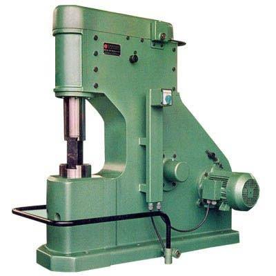
A pneumatic hammer installed in a single quantity is usually equipped with an individual compressor unit. Such a pneumatic hammer does not have a high mass of falling parts, and therefore can be used for forging small products. The pneumatic hammer has, as a rule, a C-shaped frame, which is fastened with side racks for rigidity. The punching area of the pneumatic hammer is thus open on three sides, which makes it easier to maintain.
The hydraulic hammer is of limited use. Hydraulic forging units are often used in hot sheet forging, when processing titanium alloys with low plasticity in the cold state. Die speed in hydraulic hammers lower due to differences in oil/water density compared to air/steam. The hydraulic actuator assumes increased requirements for sealing seals, otherwise its device does not fundamentally differ from other schemes of the considered installations.
Download instructions for blacksmith hammers Blacksmith KM1-25R, KM1-20R, KM1-16R
Forging pneumatic hammer is used for processing metal products by cutting, broaching, bending, knocking out various holes.
Its use allows you to perform stamping due to backing dies, it is not recommended to work with closed dies, since the hard blows of the forging hammer can cause the headstock to be repaired.
Features of the functioning of a pneumatic forging hammer are the use of air that enters the equipment compressor from the environment.
The incoming air, in the process of reciprocating action of the compressor piston, is compressed, then discharged.
The piston drives the drive-type electric motor by means of V-belts.
Also, the device of the working circuit includes: a gearbox, which helps to reduce the level of rotation of the crank, a crank shaft and a connecting rod.
If you pay attention to the presented drawings, you can see that the forging pneumatic hammer may not have a gearbox in the working circuit.
In this case, the connecting rod and the crank shaft are connected, while the shaft is equipped with a flywheel.
The pneumatic type forging machine is different from the steam-air forging equipment, in which the operation of the falling elements is supported by steam or compressed air.
Pneumatic hammer is a device in which air performs the function of an elastic air cushion.
Thanks to it, the movement from the compressor piston to the worker is not transmitted rigidly.
The number of blows that a forging pneumatic hammer can perform in 60 seconds corresponds to the number of revolutions made by the crank shaft.
The forging pneumatic hammer can be equipped with falling elements with different weights, from 50 to 1000 kg. In this case, the shock wave can be from 0.8 to 28 kJ, the speed is from 5 to 7.5 m/s, the multiplicity is 12%.
The operation of the compressor piston is performed by a stroke with one degree of freedom, which is determined by the position of the angle of rotation of the crank shaft.
The working piston is installed in the lower position, the compressor piston is in the upper position, and the striker is located on the forging.
Thus, both cavities of the compressor cylinder are combined with the atmosphere with an initial pressure corresponding to the atmospheric one.
A similar pressure is also set for the cavities of the working cylinder of the blacksmith's hammer, since they communicate with the cavities of the compressor cylinder through taps.
If you have a lot of experience and the right materials, then it will not be difficult to make a pneumatic blacksmith hammer with your own hands.
With such blacksmithing equipment available, you can decorate your own home in an original way or start a profitable business.
How the pneumatic forging device is assembled, the instruction from the video material will tell about this in more detail.
But to assemble the device of a simple blacksmith's hammer, a lot of experience is not required. Homemade equipment can function by foot or electric drive.
In the latter case, the drive is connected to the electric motor by gears.
The blacksmith's hammer should stand on a flat, solid platform, which must be prepared in advance.
To do this, the working surface is poured with concrete, digging a hole in the ground with dimensions of 2x1, with a depth of 20-30 cm.
Further instructions, according to which a home-made blacksmith hammer will be assembled, provide for the following stages of work:
- frame manufacturing;
- production of a working lever;
- assembling the blacksmith's hammer and mounting the anvil.
Construction frame device for blacksmith hammer
A channel is used to make the frame. Usually, its parameters are chosen based on which products will be processed. As a rule, a 12x8 cm channel is suitable for household equipment.
The distance at which the segments of the channel will be located from each other is selected taking into account the size of the anvil - it can be 80-100 cm.
As metal spacers, either the same channel or an iron pipe is used.
In this case, the spacer in the front of the bed - the future location of the anvil, must be mounted under the channel.
Since it is the front part of the forging plant that will be subjected to heavy loads during the working process.
The spacer at the rear of the unit must be welded close to the upper level of the channels.
The mechanism of the blacksmith hammer
At the first stage of assembling the blacksmith hammer mechanism, a lever is made. A striker is mounted at one end, the other is equipped with a counterweight.
At the same time, the design of the lever can be performed both in prefabricated and monolithic form. How to make a lever correctly can be considered in more detail in the proposed video material.
To exclude the bending of the lever at the time of strong impacts will allow the use of strip steel, but not pipes. In this case, the steel must have a thickness of at least 25 mm, a width of about 70 mm.
Having visually divided the steel strip into three parts, at the end of the first part, a hole is made from one edge of the pipe for a pipe segment, which will create conditions for the rotation of the lever.
To do this, a pipe segment is inserted and welded into the finished hole, it will act as a bearing.
With a 70 mm wide steel strip, the hole should have such a diameter that 8-10 cm remain to the edge of the strip, which will prevent premature repair of the installation due to deformation of the lever in this place.
Therefore, a 50 mm product can be taken as a pipe for the manufacture of a “bearing”.
The crossbar for the device of the lever is taken with such a diameter that will allow it to rotate freely on the axis, but not to “dangle”.
So that the lever of the forging hammer does not move during the working process, which would require repairs at the most inopportune moment, it is additionally fixed with studs.
Fasteners are installed using radial holes.
By welding, one end of the lever is equipped with a hammer, the other with a counterweight.
The drummer must be made of high-strength tool steel, otherwise there will be little sense from such a striker.
Blacksmith Hammer Assembly Instructions
Two vertical posts are welded to the bed frame, their height depends on the desired hammer impact force.
Then an axis for the arm structure is attached to the racks, which can be welded or fixed in the holes made.
It is better to use the second mounting option in order to repair the lever if necessary, it could be easily disassembled.
Then, the lever design is put on and fixed on the axis of the racks.
The anvil for the blacksmith's hammer can also be made from flat steel.
First, by welding, a frame is made from a corner right size, it is welded to the front of the bed. Then workpieces are laid on it and welded.
From above, along the perimeter of the frame, a thick a metal sheet. In this case, the surface of the anvil must have a strictly horizontal position.
Article ends useful video material on how to properly maintain and repair forging equipment.
Highly mechanized and automated. The predominant position in the production process is occupied by a forging hammer.
The forging hammer is intended for hot working, plastic deformation of forgings made of ferrous, non-ferrous metals, alloys; used in the manufacture of various parts, creating an individual design.
All sorts of classifications - according to the method of lifting the woman, the number of cylinders (single-cylinder, two-cylinder). They have different design features: with a hollow solid cylindrical rod connecting the piston with a slider or without it, a different number of racks (single-column, arched).
The device and principle of operation of the blacksmith hammer
The principle of operation is based on dynamic impacts, with devices that regulate their strength. When the transducer moves from reciprocating to rotational, the accumulated energy of the mechanical system is released. The drive uses steam (steam), compressed air (comes from the atmosphere into the compressor cylinder), gas (pneumatic, gasoline), liquid under pressure (hydrostatic), electromagnetic and gravitational fields. The blacksmith hammer is convenient to use, which is achieved with the help of a practically proven control system.
The main parts of the machine: movable (woman, rod, piston), a base fixed on a stable foundation), a frame (on which guides for moving parts are mounted), an oil or hydraulic drive, electrical equipment, a shield barrier that ensures the safety of the worker.
When assembling a blacksmith's hammer, the upper part of the striker or stamp is attached to the plunger with ball filler (weight is 20-50 percent of the mass), and their lower parts are attached to the base. The blank of the product is placed in the lower part of the striker, stamp. The upper movable part of the hammer strikes the workpiece. All the impact force falls on the base, requiring a strong foundation. Apply various modes activities: automatic successive impacts, holding over the anvil, pressing the workpiece, idling.
Features of the workflow using a blacksmith hammer
When changing the duration of work cycles, the blacksmith's hammer uses an air distribution mechanism that brings three horizontally located taps to the control panel. Top and bottom steer production process, located between them, puts the device for compressing and supplying air under pressure to a non-working mode. The device allows you to adjust the multi-ton weight of the equipment, change the pressure parameters.
The dimensions are decent, the soundtrack of the process is specific, which led to the use of an alternative machine - an electro-hydraulic press. It acts less loudly, has smaller dimensions, is more practical in the production of highly artistic forged products that require a variety of shape changes, unique configurations of blanks.
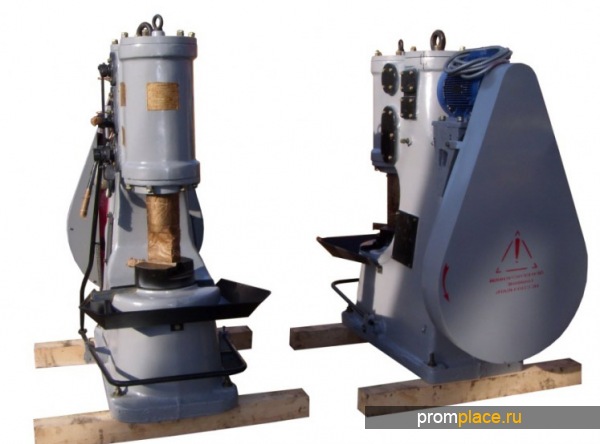
Blacksmith's hammer of various assortment is produced by machine-building domestic and foreign enterprises. Purchase opportunities are varied - from direct supplies of manufacturers to dealerships in major cities, applications on the websites of representatives are welcome. The cost depends on the brands, scope, transportation from the location of the manufacturer. For example, the KM1-16R hammer costs 115,000, KM1-20 R - 175,000, KM1-25R - 230,000 rubles.


How to understand: will the kitten be fluffy?
What kind of light alcohol can be drunk for pregnant women: the consequences of drinking
Why do the legs swell in the ankles and ankles of the feet in pregnant women: causes and methods of treatment
The wedding of Prince Harry and Meghan Markle: scandalous and secret details of the marriage (photo) The future marriage of Prince Harry year NTV
How to close white plums for the winter