Good day, gentlemen, artisans and contemplators!
We bought a machine, it was made to order at the 777 firm in Kamensk shakhtensky, for the needs of production. A lot of points were discussed that had to be fulfilled, and on which a bolt was subsequently hammered by the manufacturers. When setting pulses to stepper motor the tuners did not even have a ruler, which made it immediately clear that the path of development would be long and thorny. And I really hope to pass it with dignity with your help. I will begin to present in order
The machine was made for slotting grooves. And the first groove of U-40 mm on X-10 mm showed that the machine does not cut it exactly along the circumferences, and along the X-axis it cuts not 10 mm, as it was drawn in Art Himself, but 9 mm.
I decided to start troubleshooting with the fact that the machine did not cut the circles evenly. Not an oval, but as if there is an aiming at the engines. I grounded the machine and drew a circle with a pencil in place of the cutter with the inverters turned off. Eliminating interference, the drawing remained the same intermittent. The post processor used was G-code arcs_mm. (Tab)
The post was selected G-code_mm. (Tab) And the machine began to cut the circle already with an oval with a mixing of 1 mm in X (circle diameter 80 mm) and small intermittent steps. and at the end of the work, return from the beginning to the return point which I indicated in Art Itself and then immediately to zeros in X.Y and turn off the spindle. This can be adjusted manually, but I would like to know how to change the post so that it does not add the return to zero command and does not turn off the spindle.
I began to study the topics in order to understand what is the fault of this not before cutting the setting of the machine or the wrong post and took measurements of the mixing of the machine manually in Vector Control.
Bottom line: when moving manually along Y by 25 centimeters of travel, the machine moves 0.3 mm, and when moving along X by 15 cm, it did not reach 0.1 mm.
On both axes there is a servomotor and a toothed rack (the same). Art Kam 9.1. Managing. program NcStudioV5.5.60.
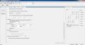
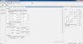
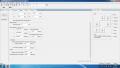
I am attaching screenshots with NcStudio settings
Thank you all in advance for your help
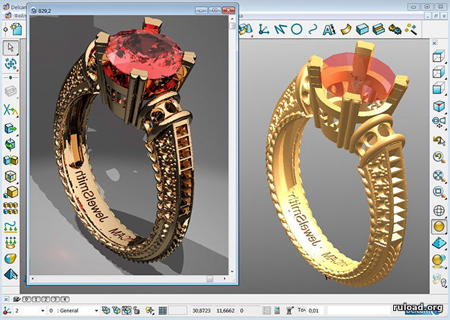
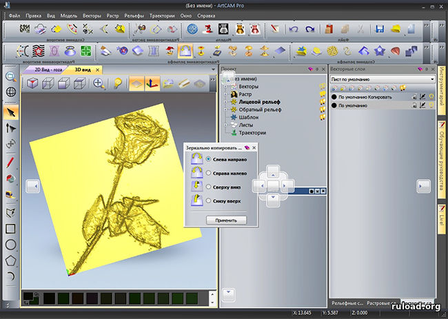
This page provides an opportunity to download ArtCam via torrent. It is a 3D modeling environment with the ability to create programs for machine tools.
The main feature of Artkam is the ability to make a three-dimensional out of any two-dimensional object. There are many tools available to accomplish this function. You can, for example, select the shape of a surface (plane, sphere, pyramid, and so on) and extend any flat contour to it. There is a library of ready-made shapes. They are sized and added and subtracted to create new shapes. All kinds of deformations are also available.
With the help of special algorithms, you can simulate different type coverings in ArtCam rus. The program interface is very simple and intuitive. There is Russian in the menu, as well as detailed help and training materials in it.
Import vector and bitmap images in all popular formats. Save finished projects in generally accepted standards. The program comes with a special extension for working with jewelry... There are many typical elements (over 300) for rings, chains, etc.
For the prepared product, it is possible to create a program code for CNC machines. In this case, you can immediately recreate the object in reality. This function will be indispensable in production.
Video review and lessons Artcam
Screenshots


System requirements for Artcam
OS: Windows 7/8/10 / XP
CPU: Intel Core i7 or AMD FX
Video card: NVIDIA Quadro or AMD FirePro
RAM: 6 GB
Version: 2012 Build 359
Type: Simulation Software
Release date: 2015
Developer: Delcam
Platform: PC
Edition type: final
Interface language: Russian
Medicine: included
Size: 5.1 GB
Installing Artcam on your computer
- Run the installation file
- Install the program to the desired location (be sure to install the drivers)
- Copy the Exec and Exec64 files from the _Crack_ / ArtCAM 2012 SP2 / folder to the program directory
- Start using.
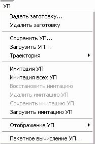
Use of UE
ArtCAM Pro provides a set UP for processing two-dimensional and three-dimensional models in whole or in part. They are available on the home page UP, which can be opened by clicking on the UE tab.
Also on the home page UP you can find control buttons and changes to the created UE. For more details, see the section Managing and changing UP .
Management and change of PM
Management and change of PM
Via home page UP you can manage and edit the NC required for processing the model.
Namely:
Combine multiple computed UP in one.
Set processing order UP selected for combining.
Change one or more calculated UP.
Create one copy of one or more computed UP.
Create a block of copies of one or more computed UP.
Set the order of processing for all UP containing profile passes.
Change tool processing parameters during creation UP or after. For more information, see Changing tool processing parameters.
Save UP... For more details, see the section Saving NC.
Edit settings UP... For more details, see the section Editing NC.
Delete UP or group UP... For more details, see the section Deleting a UE.
Calculate UE separately or as part of a package. For more information, see Single NC calculation and Batch calculation. UP.
View Information about UP and calculate the approximate processing time. For more details, see the Information on UP.
Add, edit or delete instruments from the Instrument Base. For more information, see Using the Tool Base.
Modify the preset. For more information, see Modifying a preset.
Remove blank. For more information, see the section Deleting a Preset.
Save the UE as a template. For more details, see Creating a Template UP.
Load NC template. For more details, see Loading a Template UP.
Set the processing order. For more details, see the section Setting the order of NC processing.
Tools for working with UP can be found in the section Operations with UE on the main page of the UP:

Additional tools for working with UP can be found in the sectionUP of the main menu.
Selection of UE
Selection of UE
You can control the calculated 2D or 3D UE is the same as vectors in ArtCAM Pro.
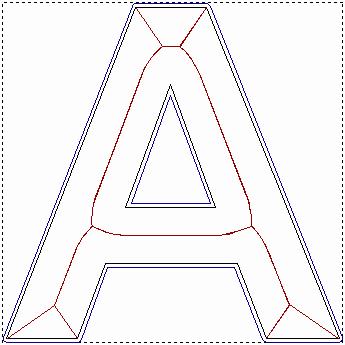
It is possible to transform, copy and edit passes inside the NC, provided that a 2D preview was created during the calculation. The NC view can only be shown in the 2D view window in dark red.
To select the NC view in the 2D view window:
2. Click to select the desired NC image. It will be highlighted in blue and framed.
For example, in the picture of the profile UE shown below:
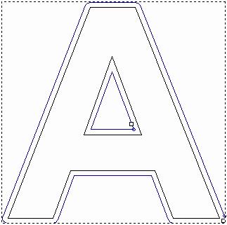
You can set the default color for the selected NC image on the ArtCAM Settings page.
To select more than one NC image in the 2D view window:
1. Make sure you are in vector selection mode. For more information, see the section Selecting vectors.
2. You can select several NC images in one of the following ways:
Click and move the cursor to enclose the desired NC images with a rectangle. They will be highlighted in blue and will be framed.
Hold the key Shift on the keyboard and select in turn all the necessary NC images. They will be highlighted in blue and will be framed.
To select a UE from the list on the main page of the UE:
1. Click on the name of the tool. It will be highlighted in blue.
Editing a Profile Pass
You can edit any profile pass of the selected NC using the Transition Parameters page.
You cannot edit the NC profile pass without using the NC viewer. Make sure the Create option is 2D vector by NC is always selected when creating NC.
To open this page in the Assistant window:
1. Select the NC view containing the desired pass. For more details, see the section Selecting NC.
2. Click on the UE UE tab.
3. Click the button Transition options In chapter 2D NC.
On the page Transition options there are three options for editing passes, but only one setting can be displayed at a time:
Transitions- This option allows you to add vias to the selected profile pass. For more information, see the section Adding transitions.
starting point- This option allows you to change the position of the starting point of the selected profile pass. For more information, see Changing the starting position.
Leads- This option allows you to add leads to the selected profile pass. For more details, see the section Adding leads.
Adding transitions
Adding transitions
Transitions are used for the workpiece rel
In the given position of the tool in the direction of the Z axis, leaving allow to hold the image After the part has been simply broken off.
You can add transitions to any profile pass of the computed NC, provided that a 2D preview was created during the computation. Profile passes are included in NC programs such as profiling, edge machining, machining along vectors and insertion (die-punch).
To add a transition to a profile pass:
1. Press the button Selecting vectors
2. In the window 2D view, select the image of the passage to which you want to add transitions. By default, the UP image will be highlighted in blue. For more details, see the section Selecting NC.
3. Click on the bookmark UP to open the home page UP.
4. Click the button Transition options In chapter2D NC to open the page Transition options.
5. Select an option Transitions
6. Set the length of each transition in the field Length Transition a.
7. Set the thickness of each transition along the Z axis in the field Transition Height.
8. To add triangular vias that are not associated with branches or leads, select the option 3D transitions.
Three-dimensional transitions have a protruding shape, triangular or pyramidal. This shape reduces the cross-section and overall surface of the transition, and the disconnection with leads and outlets prevents traces on the surface.
Default transitions ... 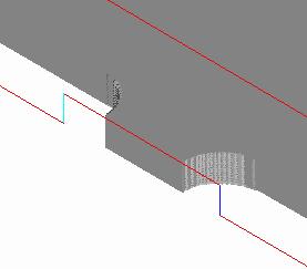
3D transitions ... 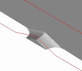
9. To set the method for adding transitions, in the section Adding transitions in the profile select the option you want:
Constant quantity- inserts the specified number of evenly spaced 3D transitions into the selected profile path.
When choosing this option, set the desired amount of 3Dtransitions in the Number field.
Constant interval- insertion of 3D transitions at a specified distance from each other.
When this option is selected, set the distance between transitions from the center of each 3D transition in the field Distance
Next, set in the field Min. number minimal amount 3D transitions in the selected trajectory, regardless of the previously specified distance between them. To limit the number of clicks, set the maximum number in the field Max. number.
10.Click the button Create transitions to add transitions to the selected profile pass.
11.Click the button Close to return to the main page Assistant.
Changing the starting position
Changing the starting position
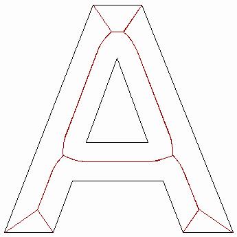
The start point of the profile path defines where the tool enters the workpiece when machining the model. The starting point is highlighted in green and circled in blue.
To reposition the start point relative to a specific anchor point:
1. Press the button Selecting vectors For more information, see the Vector Tools section on the Assistant main page. For more information, see the section Selecting vectors.
2. In the window 2D views select the image of the passage for which you want to replace the starting point. By default, the UP image will be highlighted in blue. For more details, see the section Selecting NC.
3. Click on the bookmark UP to open the home page UP.
4. Click the button Transition options In chapter2D NC to open the Navigation Options page.
5. Select the Start point option to display the corresponding settings.
6. In the Ground control section, select one of the four control points, relative to which you want to set the position of the starting point of the selected profile path:
Center of gravity- This option sets the center of mass of the vector from which the trajectory is created as the reference point.
Center of bounding box- This option sets the center of the bounding box for the selected profile path as the reference point.
When this option is selected, selection buttons appear in the Position section. They show the possible positions of the starting point on the selected path relative to the reference point.
You can specify the starting point at the top, bottom, right, or left of the current position, depending on the cutting direction of the selected profile path.
Greatest or smallest value X or Y- This option specifies the point of the profile path with the largest or smallest X or Y value as the reference point, depending on the cutting direction.
Selecting this option will display selection buttons in the section Position... They show the possible positions of the starting point on the selected path relative to the reference point.
You can specify the starting point at the top, bottom, right, or left of the current position, depending on the cutting direction of the selected profile path.
7. In the section Position select one of the start point location options. You can also click on the starting point and drag it to the desired position.
8. Click the button Apply to set the new position of the start point.
9. Click the button Close to return to the main Assistant page.
You can set any point (node) of the selected vector as the starting point. For more information, see Changing the starting point. This will set the starting point when creating the NC.
Adding leads
Adding leads
Leads are used to prevent traces on the workpiece when the tool enters and exits.
Instead of vertically burying and lifting the tool on contact and exiting the workpiece, the tool approaches and retreats a short distance from the start / end of the profile pass. This is either the starting point of the original vector, or the midpoint of its longest segment.
You can add leads to any profile pass of the calculated NC, provided that during the calculation was created 2D viewing. Profile passes are included in NC programs such as Profiling, Edging, Machining along vectors and Insertion (punch die).
T You can also add leads to the profile path when creating the infeed program itself.
To add leads to a profile pass:
1. Press the button Selecting vectors For more information, see the Vector Tools section on the Assistant main page. For more information, see the section Selecting vectors.
2. In the 2D view window select the image of the passage to which you want to add leads. By default, the UP image will be highlighted in blue. For more details, see the section Selecting NC.
3. Click on the UE tab to open the main page UP.
4. Click the button Transition options In chapter2D NC to open the page Transition options.
5. Select an option Leads to display the corresponding settings.
6. If you do not want to add bends, select the No bend option.
7. Set the lead-in length in the field Lead Length (D).
8. Set the distance from the start / end point of the filing pass, which will take the processing, in the field Clearing (O)... This will help in the future to create a smooth ending of the machining path.
9. Select the approach method using the selection buttons:
Linearly- Select this option for straight tool approach and tool retraction. If you select the Linear option, specify the angles of the linear leads in the Entry angle and Exit angle fields.
When editing leads associated with profile cuts for machining within a specified area, the lead length or arc lead radius is now taken into account.
When calculating a linear lead-in, ArtCAM checks that the lead-in length remains within the profile boundary. If the program encounters an intersection with a boundary, the lead-in length is cut until the intersection is eliminated.
When calculating an arc approach, ArtCAM checks that the approach radius remains within the profile boundary. If the radius crosses the boundary, the lead is converted to a linear lead with a length that does not cross the profile boundary.
In an arc- Select this option to approach and retract the tool in an arc. If this option is selected, specify the radius of the arc in the Radius box (R).
Value in the field Lead Length (D) must be less than or equal to the value in the field Radius (R) otherwise, when trying to Apply leads to a profile pass, the following message will appear:
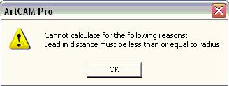
Click on OK to close it.
10.Click the Apply button to add leads.
11.Click on the Close button to return to the main page.the page Assistant.
Changing tool processing parameters
In ArtCAM Pro, you can change tool options as follows:
When creating a UE, on the UE page. For example, on the Profile Processing page. For more details, see Changing processing parameters when creating an NC.
After creating the UE, using the main page of the UE. For more details, refer to Changing the processing parameters of the created NC (on page 367).
You can also change the default settings of a tool from the Tool Base. This method can only be used before selecting the NC. For more information, see the section Editing a tool.
Changing processing parameters when creating NC
You can change the processing parameters of tools when creating a NC.
For this:
1. When in the window Assistant page opened UP, display the processing parameters of the selected tool by clicking on the arrow in the tools section.
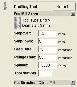
For example, if you select a 3mm Profile Tool End Mill, the Tools section of the page Profile processing looks like that:
2. Now you can set new processing parameters:
To change the step of the selected tool, specify a new distance between adjacent passes in the Step field.
To change the depth of the selected tool, set the maximum depth in the field Depth per pass. Deepening results in multiple machining passes.
To change the feed of the selected tool, define the tool travel relative to the workpiece in the field Working feed.
To change the infeed of the selected tool, specify the tool travel along the Z axis in the Plunge Feed field.
To change the spindle speed, specify the new speed in the Rotation Frequency field. The spindle is the part of the machine that rotates during operation. It holds the tool on the cutter. On the machine, it holds the workpiece.
To assign a number to the selected tool, click on the Tool Number list box and select desired number... The number must correspond to the position of the tool on the tool changer of the machine.
Changing the processing parameters of the created NC
When the NC is created, you can change its processing parameters, except for Depth and Pitch. You can also modify such path alignments as Return Point and Safety Z Height.
To change machining or toolpath parameters:
1. Click on the bookmark UP to open the home page UP.
2. Select the tool in the list under the name of the NC, the parameters of which you want to edit. For more details, see the section Selecting UP .
For example, a 3mm Profile Tool End Mill looks like this:

3. Click the button Edit Options to display the machining options for the selected tool.
For example, when selecting a 3mm Profile Tool End Mill, Section Parameters looks like that:

4. Processing parameters can be changed as described in the section Changing processing parameters when creating a NC.
You can also change:
The name of the instrument.
Safety height in Z, i.e. the level at which the tool moves rapidly between path segments.
The Return Point (XYZ) of the tool.
A comment about a trajectory is usually its name.
The color of the visualization of the UE filling.
If you have a machine with a rotary coordinate, you can make the machine rotate the model. ArtCAM Pro allows you to create a single NC including front and reverse NC. The return path is preceded by a rotary motion that turns the workpiece to the desired position before machining.
To use automatic rotation, specify the angle of the rotated NC in the A axis angle field. The angle is added to the NC name and is shown in brackets. You need to connect the paths together using a postprocessor that supports rotation. For example, Model Master Indexer.
5. Click the button Apply.
Preservation of UE
Preservation of UE
You can save the NC along with the model as an ArtCAM model file (* .art). See Saving a Model for details.
You can export the NC data to a file suitable for the machine, as explained below.
To save NC data to a machine-specific file:
1. Click on the UE tab to open the main page UP.
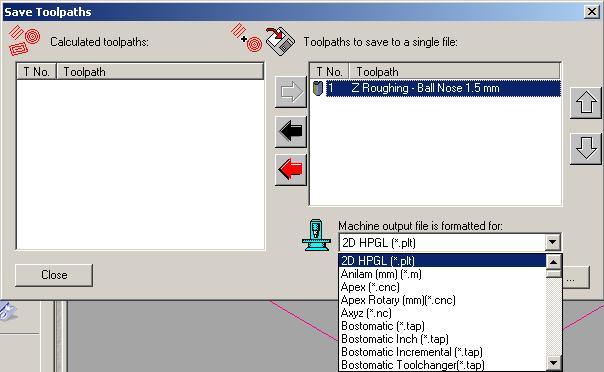
2. Click the button Save UE In chapter Operations with UE to open the dialog Save UE:
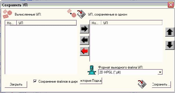
3. Select from the list in the window Calculated UE those UP you want to save to a file suitable for the machine.
To select more than one NC, hold down the Shift on the keyboard and click on each in turn.
4. Press the right button to transfer the selected NC to the NC window, saved in one file.
5. Make sure the feeds are in the correct order.
Use the up and down buttons to set the order in which the NC is saved. Each click up or down moves the selected NC unit one position.
Click on the black left button to transfer the selected NC back to the Computed NC window.
Click on the red left button to transfer everything UP back out the window Calculated UE.
6. Click on the NC Output File Format list box and select the required format.
If you have not selected a swap directory, click the Swap Directory ... button to open the Find Folder dialog box. Select the desired folder and click OK to set the swap directory.
If you do not need to save the file corresponding to the machine to the swap directory, make sure that the Save files to swap directory option is disabled.
9. Write a name for the file in the File name field.
10.Click on the File Type list box and select the file type in which you want to save the NC.
12.Click the Close button to close the windowSave UE.
You can also save the NC from the 2D view window or 3D view. In the main menu, select the NC> Save NC option to open the Save NC dialog box. For more information on the Save UE dialog box, see the beginning of the section.
Editing NC
Editing NCYou can change the settings of any created NC.
To change settings using the 2D View window:
1. Press the button Selecting vectors For more information, see the Vector Tools section on the Assistant main page. For more information, see the section Selecting vectors.
2. Select the image of the NC that you want to edit. For more details, see the section Selecting NC.
3. Right-click to display the NC edit menu and select the Edit NC option to display the NC settings in the Assistant window.
For example, if you select a profile NC and the Edit NC option, the Processing by profile page will open in the Assistant window.
You can also edit the NC settings using the NC main page:
1. Press the button Selecting vectors For more information, see the Vector Tools section on the Assistant main page. For more information, see the section Selecting vectors.
2. Click on the NC tab to open the NC main page.
3. Select the NC that you want to edit from the list. For more details, see the section Selecting NC.
4. Click the button Edit NC For more information, see NC Operations to open the NC page in the Assistant window.
Deleting UE
You can delete a created NC or a NC group.
UP group is a UE, using more than one processing tool. For example, an edge engraving program uses engraving and profiling tools.
Deleting UE
Deleting UE
To remove the NC from the 2D view window:
1. Click the Select Vectors button in the Vector Tools section on the main page of the Assistant. For more information, see the section Selecting vectors.
2. Select the image of the UE that you want to delete. For more details, see the section Selecting NC.
For example, if you delete a profile cut from an edge machining program, it will look something like this:
3. Right-click to display the NC edit menu and select the Delete NC option.
In our example, you can see that the profile pass has been deleted:
Deleting a NC group
Deleting a NC group
To delete a NC group using the 2D view window:
1. Press the button Selecting vectors For more information, see the Vector Tools section on the Assistant main page. For more information, see the section Selecting vectors.
2. Select the image of the UE that is part of the group. For more details, see the section Selecting NC.
The selected part of the NC group will be highlighted in blue and will be framed.
For example, when you select a profile pass from an edging NC to be removed, it will look something like this:
3. Click the right mouse button to display the NC edit menu and select the option Delete NC group.
In our example, you can see that both the profile pass and the midline pass have been removed:

You can also delete the NC using the main page of the NC by selecting the NC group from the list and clicking on the Delete NC button in the Operations with NC section.
In this section, you will create a simple control program using a previously prepared relief. Setting parameters mechanical processing This example is for demonstration purposes only. It is assumed that you already know how to operate your machine and that your knowledge is enough to choose the right tool and technological parameters.
If you are unsure of any aspect of the operation of your machine, consult a qualified technician or contact your machine supplier.
Discovery of the Relief
Machining in ArtCAM begins after the 3D relief is obtained. In this example, you are using a project created by simply pasting a few elements from 3D templates found on the ArtCAM CD.
1. Using the command Close (Close) from the menu File (File) close all projects you worked with before.
2. Select the command Load - Replace (Load - Replace) on the menu Relief (Relief).
3. Download the file Dragbadg.rlf the Examples / overview directory.
Since there is no image in the 2D window, ArtCAM creates a grayscale black and white image in the 2D window.
Creation of UE
For creating control program used Toolpath Manager (UP Manager).
1.Switch to dashboard Toolpath(UP).
2. Click the icon Material Setup (Quest Blanks).
4. Enter in the field Name (Name) name of the toolpath - Simple Raster... This name can be up to 32 characters long, including spaces.
5. In the section Roughing tool press the button Select.
6. In the opened dialog box Tool Groups Database choose a milling cutter from the metric tool for aluminum Ball Nose 1.5mm and press the button Select.

7. Move to the section Strategy (Strategy).
8. Select the type of strategy - Raster (Raster Processing).
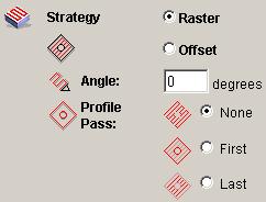
For this example, all settings can be left as default.
9. Review other bookmarks.
The values you set are for demonstration purposes only. If you want to process the model from this example, select the values that are appropriate (and save them!) For your machine. If in any doubt, consult a qualified technician or your machine supplier for help.
10. At the very bottom of the window Z level roughing press the button Now against Calculate.
You will see how ArtCAM creates a control program in the form of a red line in the 3D window. If you click the mouse button, ArtCAM will give you the option to opt out of creating a toolpath.
As soon as the control program has been created, ArtCAM signals this - a red mark appears next to the name of the tool path on the tab Project.
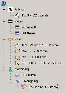
The control program is created according to the current relief in the 3D view window.
11. Click the icon Object To Draw (Items to Display).
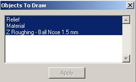
Now you can examine the toolpath in the same way as described in the chapter Controlling the 3D View Window section 3D Relief Creation... Now you can save the NC in the format of a specific CNC rack.
Saving NC for a specific CNC rack
1. Click the icon Save Toolpath (Save UE) on the toolbar Toolpath (UP).
A dialog box appears Save Toolpaths (Save UE). If you have created several NC programs or have a machine with automatic tool change, you can organize and combine your NC programs using this dialog box. For our example, which consists of only one NC program, you can simply select the output file format for the CNC machine and press the button Save (Save).
The output file is saved in the format of a specific CNC machine. For details, see the relevant section in On-Line Help Manual.


How to understand: will the kitten be fluffy?
What light alcohol can pregnant women drink: consequences of consumption
Why do legs swell in the ankles and ankles of feet in pregnant women: causes and methods of treatment
The wedding of Prince Harry and Meghan Markle: scandalous and secret details of the marriage (photo) Future marriage of Prince Harry year NTV
How to close white plums for the winter